
The system measures the following parameters: longitudinal profile of left and right rail, alignment of left and right rail, track gauge (dual measurement), superelevation and cross level, twist, curvature and curve radius, gradient and position using GPS.
Also measured and recorded are measuring speed, distance, and events (e.g. tunnels, bridges, etc.) and the ambient temperature.
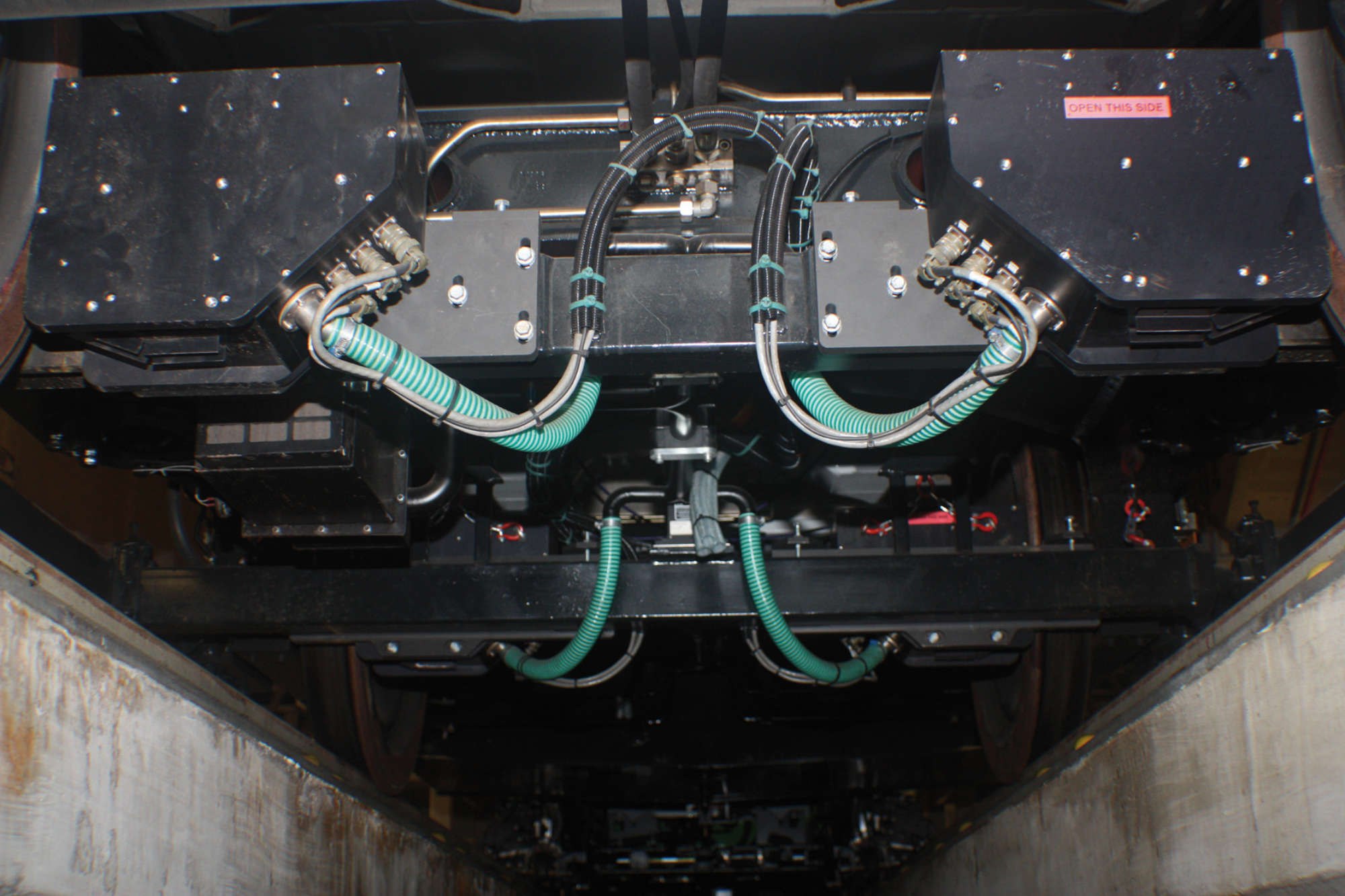
The track geometry measuring system consists of the following units: the inertial measuring unit (IMU), two optical gauge measuring systems (dual OGMS) and the navigation system (navigation computer with integrated GPS receiver, GPS antenna).
The recording car itself is equipped with a measuring frame which is fixed to the four axle boxes of a bogie. The IMU and the four measuring sensors for the dual track gauge measurement are mounted on the measuring frame. This ensures that the measuring frame, the IMU and the sensors are always guided parallel to the rail surfaces, therefore the measuring frame can be used as a reference plane for the track geometry measurement.
As the bogie applies a load to the track during the measuring run, the track geometry is measured under realistic loading conditions. It is not necessary to compensate for suspension deflections or vehicle body movements. The system guarantees highest measuring precision from standstill of the vehicle up to the maximum speed.
Conventional inertial measuring systems require minimum measuring speeds, dependent on the wavelength to be measured, in order to provide accurate measurements. The minimum measuring speed for a wavelength of 30 m is 27 km/h, and even 135 km/h for a wavelength of 150 m. Under true operating conditions this requirement cannot always be guaranteed. If the posted track speed is less than the minimum required measuring speed or the selected measuring car cannot reach the minimum measuring speed for the selected wavelength, the results are measuring gaps.
Plasser & Theurer avoids these problems by using the inertial measuring system with the integrated navigational solution. Only this innovation made the inertial system usable for measuring track geometry under all measuring speeds. The measuring unit has no moving parts and is therefore very sturdy. It is connected directly to the axle bearings via the measuring frame, which means that the geometry is measured directly. The combination of inertial and navigation measurement supplies accurate measuring data not only at high speed but also at low speed. Track geometry data are recorded three-dimensionally and the track gradient is also measured in addition to the standard track geometry parameters.
The IMU contains three acceleration sensors and three rate gyros to measure changes in angle. By picking up the movements during the run, the IMU supplies earth coordinates of a space curve which represents the exact position of the track in space. The two gauge measuring systems on the measuring frame create the horizontal reference between IMU and the rails. In order to make a correct assessment of the track condition on high-speed lines, it is absolutely essential to record the track geometry as a space curve. Chord measurements alone would not be sufficient at all.
An accurate localization of the measuring results is absolutely essential for useful track recordings. Manual event marking by pressing buttons gives an accuracy of around 6 m but there are circumstances when this method can hardly be used or not at all, for example at night.
The DGPS* location synchronization is an integrated feature of the Plasser & Theurer track geometry measuring system. It fully automatically adds the exact location data acquired to the track measuring data thereby eliminating the manual synchronization.
The track location accuracy when using DGPS is 0.4 m. The GPS coordinates come from the GPS receiver or, in areas with no reception, such as tunnels, from the IMU until GPS reception is resumed.
All space curve coordinate data are recorded by the on-board computer system. The distance measuring resolution is determined by the distance encoder. The encoder generates 10,000 pulses per wheel turn. Dependent on the distance interval (set by the operator, e. g. every 25 cm) the processing unit retrieves the current measuring data from the subsystems and records them in a data base. To every measurement the navigation system supplies the exact location data which are also stored in the data base.
All required track geometry parameters are derived from this precisely localized space curve. In real time an exception report is issued, listing all defects which are outside the defined tolerances.
One of the fundamental requirements of track recording is to record the track condition under load because the track geometry at rest naturally gives no information as to how the track will behave under realistic operating conditions.
Mounting the measuring sensors on the measuring frame, which is firmly connected to the bogie, fulfills this requirement since the track is measured under the load applied by the recording car.
The following reproducible accuracies are documented:
The Plasser & Theurer track geometry measuring system is capable of measuring at any chosen speed up to 300 km/h. Unlike other conventional inertial measuring systems, it requires no minimum speed to measure accurately.
A major advantage of the Plasser & Theurer track geometry measuring system is its almost unlimited flexibility for the display of measuring data. For example, the alignment and longitudinal profile of both rails can be displayed in real-time simultaneously both as space curves for three freely selectable wavelengths and also for three freely selectable chord lengths. All parameters can be monitored during the measuring run in any desired combination on any linked terminal. The software offers over 100 different mathematical and railway-related calculations. In addition, it is possible to emulate measuring systems already in use and working with other measuring principles in real-time as well. In this way, older recordings can be compared with the current data.
* differential GPS
