
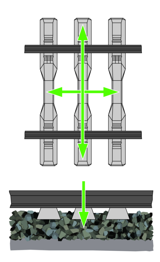
Track resistance to lateral, longitudinal, and vertical displacement. Track geometry stability depends, among other things, on the degree of ballast compaction. It is an important factor for providing safe and efficient railway transport.
Describes how long the produced track geometry will last. The higher the track geometry stability, the longer the optimal track geometry is maintained, which reduces the maintenance work required.
Unintended horizontal or vertical track deformation that poses a major safety risk. One of the most common forms of track buckling is lateral buckling of the track panel which is usually caused by heat due to the thermal expansion of the rails when the track can no longer absorb the large internal longitudinal compressive forces.
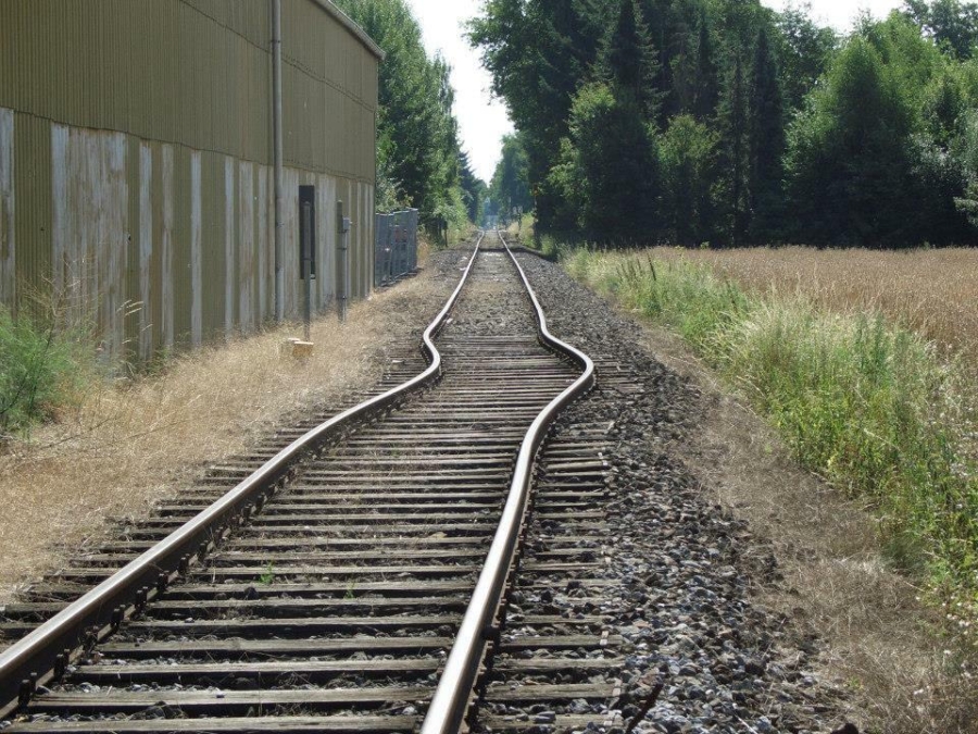
Source: ABproTWE (commons.wikimedia.org), „Gleisverwerfung ehem Bf Gütersloh Ost 04 08 2013“, creativecommons.org/licenses/by-sa/3.0/legalcode
Initially, the ballast bed does not yet have the optimum compaction density throughout. Therefore, the forces and vibrations caused by rail traffic cause a settlement process where the ballast stones settle closer to one another over time. This process is known as ballast consolidation.

The stresses exerted by train traffic on the track panel and ballast bed are indicated in load tonnes (Lt) and is calculated from the sum of the axle loads of the passing trains.
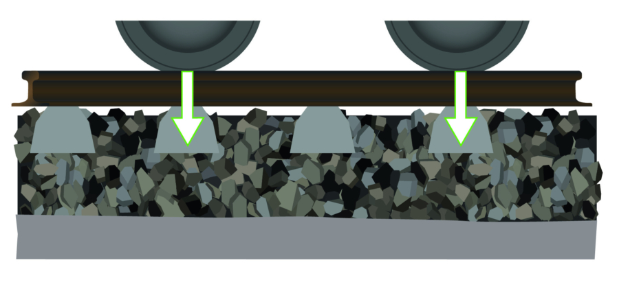
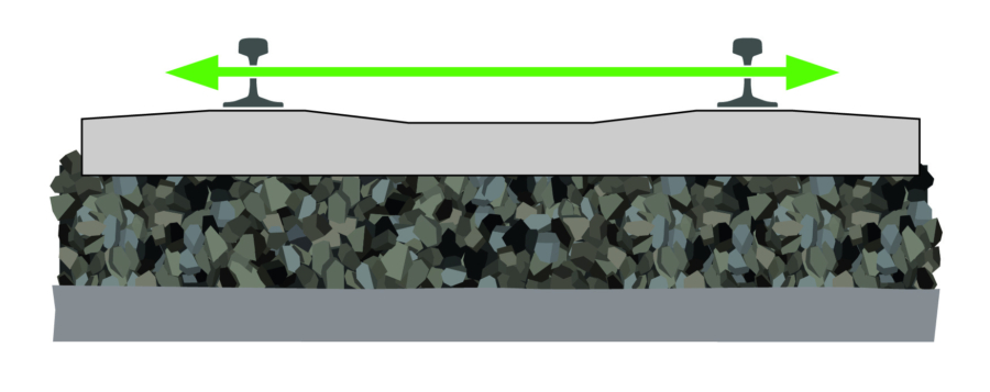
The LTR counteracts the transverse forces and prevents the lateral displacement of the track panel. It is a significant parameter for the alignment of the track and for the track geometry stability, particularly for the lateral stiffness. If the LTR is too low, track buckling can occur.
In the following, the most common methods are explained briefly. Even though all methods are legitimate, the single-sleeper method often forms the basis for standards and regulations.
The individual measuring methods used by operating companies and institutions to determine the LTR can vary. However, the International Union of Railways (UIC) has confirmed the comparability of the measuring results (International Union of Railways (UIC)): Lateral Track Resistance (LTR), Edition 2019).
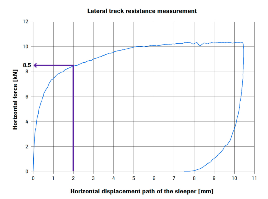
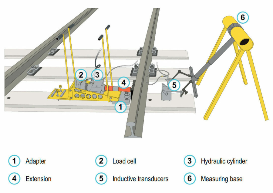
In a first step, the rail fastenings of the sleeper to be examined are removed to decouple it from the rail. A hydraulic inspection device displaces the unloaded sleeper. The rail serves as an abutment. Measuring instruments record the displacement path and the force required.
Instead of displacing a single sleeper, a track panel or pre-fabricated track panel with several sleepers is displaced against firm abutment. This method is based on the fact that the lateral forces exerted during rail traffic are distributed to several sleepers. The LTR of a track panel with multiple sleepers is lower than the sum of the resistances of single sleepers.
In some countries, Track Loading vehicles (TLV) are used. To determine the LTR under load conditions, they apply a static or dynamic vertical load to the track while introducing a growing lateral force.