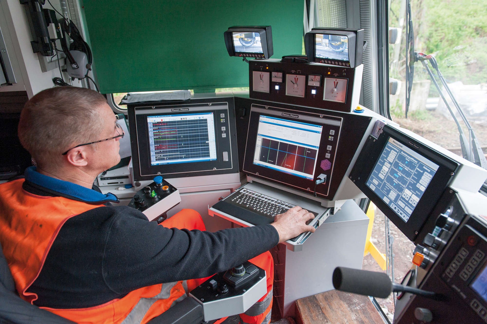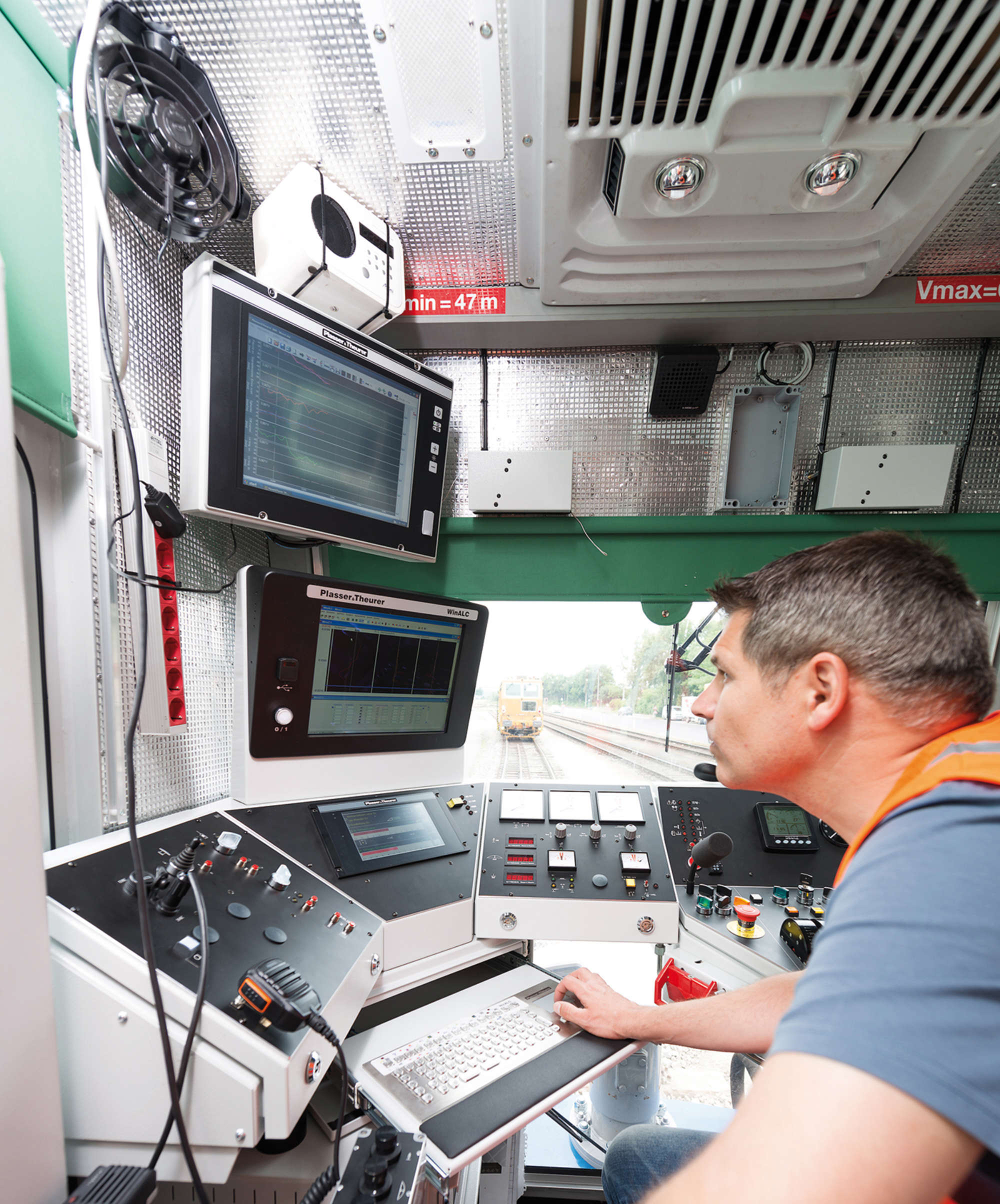
The right control of a track maintenance machine is crucial to the high-quality maintenance of tracks and turnouts. A range of electronic equipment and control equipment enables the operating staff to pay their undivided attention to the tasks crucial for the completion of the work sequences.
The high demands placed on the track geometry quality and the tight acceptance tolerances for tamping work require utmost precision for the work sequences. To meet these requirements, a guiding computer with specially developed software is used to control the tamping machine.
The SmartALC is the latest stage of development. This article provides general information also applying to the Win-ALC. In the following, we therefore use the term “ALC”. An industrial-grade panel PC is used as hardware, with the PC fitted straight onto the back of the display thus forming a compact unit. A stainless steel keyboard with integrated touch pad is used for user input.
The software was developed with the objective of making its use as easy and efficient as possible for the machine operator. By using the Windows user interface, operation is familiar and intuitive.
For track data analyses, production planning or training purposes, it is also possible to install the ALC software on standard office PCs.
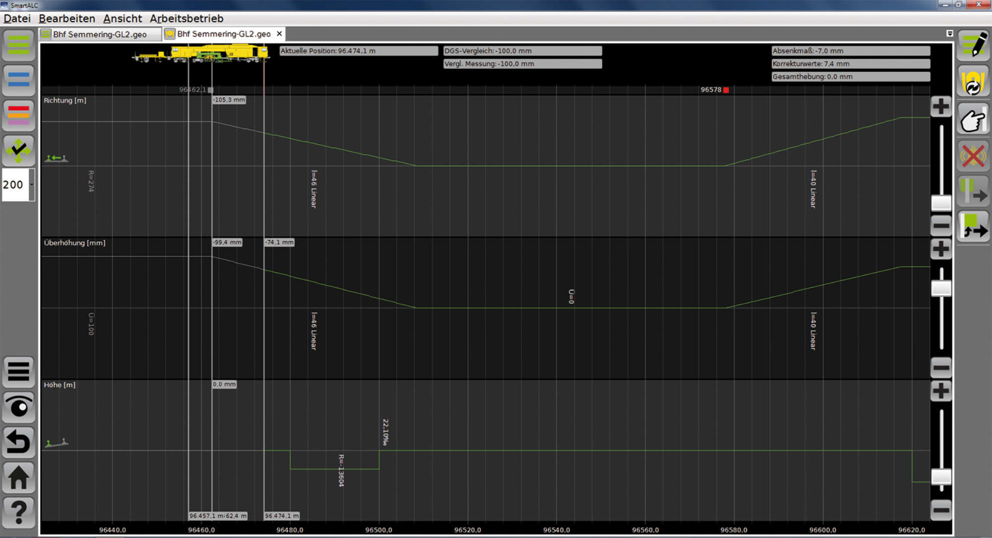
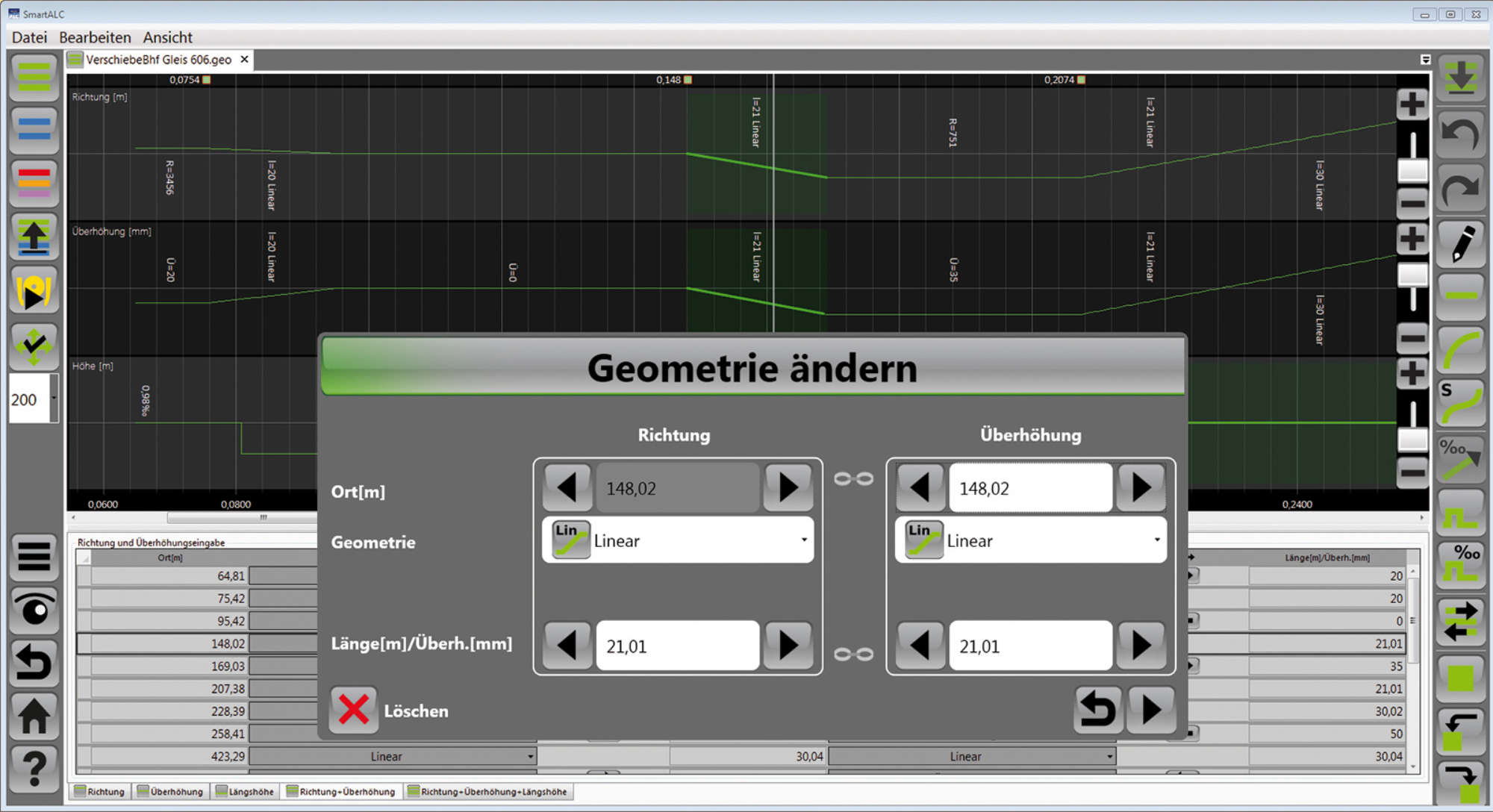
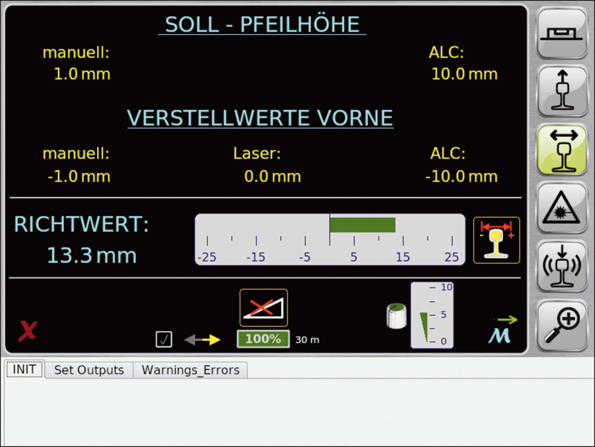
Geometry and correction data can be input graphically or in table form. In addition, data can be read in from storage media provided by the infrastructure operator.
Two work modes are available:
The ALC software is able to distinguish between the various track categories and calculates the correction values within the defined deviation limits. Points of restraint such as bridges or level crossings are included in the calculation. The same applies to thresholds for maximum lifting and lining values.

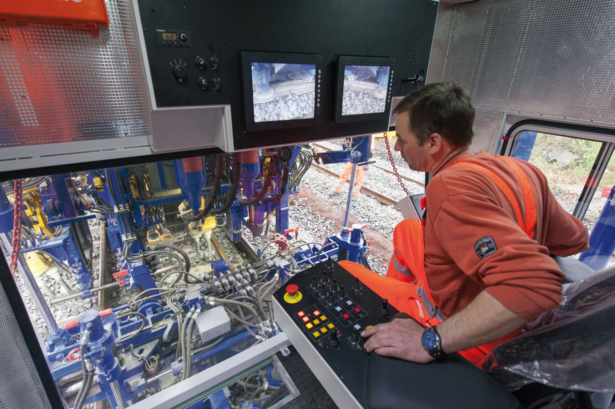
The results of the measuring run and the work performed are displayed simultaneously for better comparison.
Another important use of the ALC is the removal of individual short-wave track geometry faults (6 to 15 m) which can be removed locally in spot fault mode. An accurate survey is made to ascertain the characteristics of the spot faults. The required correction values are calculated independently for the left and right hand rail and adapted to the prevailing track geometry.
Following maintenance and a subsequent measuring run, an acceptance chart is printed showing the exact length of the tamped track section and paramters such as longitudinal level, twist, cross level and alignment values.
Various detail functions ensure the efficient, safe and comfortable control of the tamping operation, offering special advantages for the operation of Plasser & Theurer tamping machines.
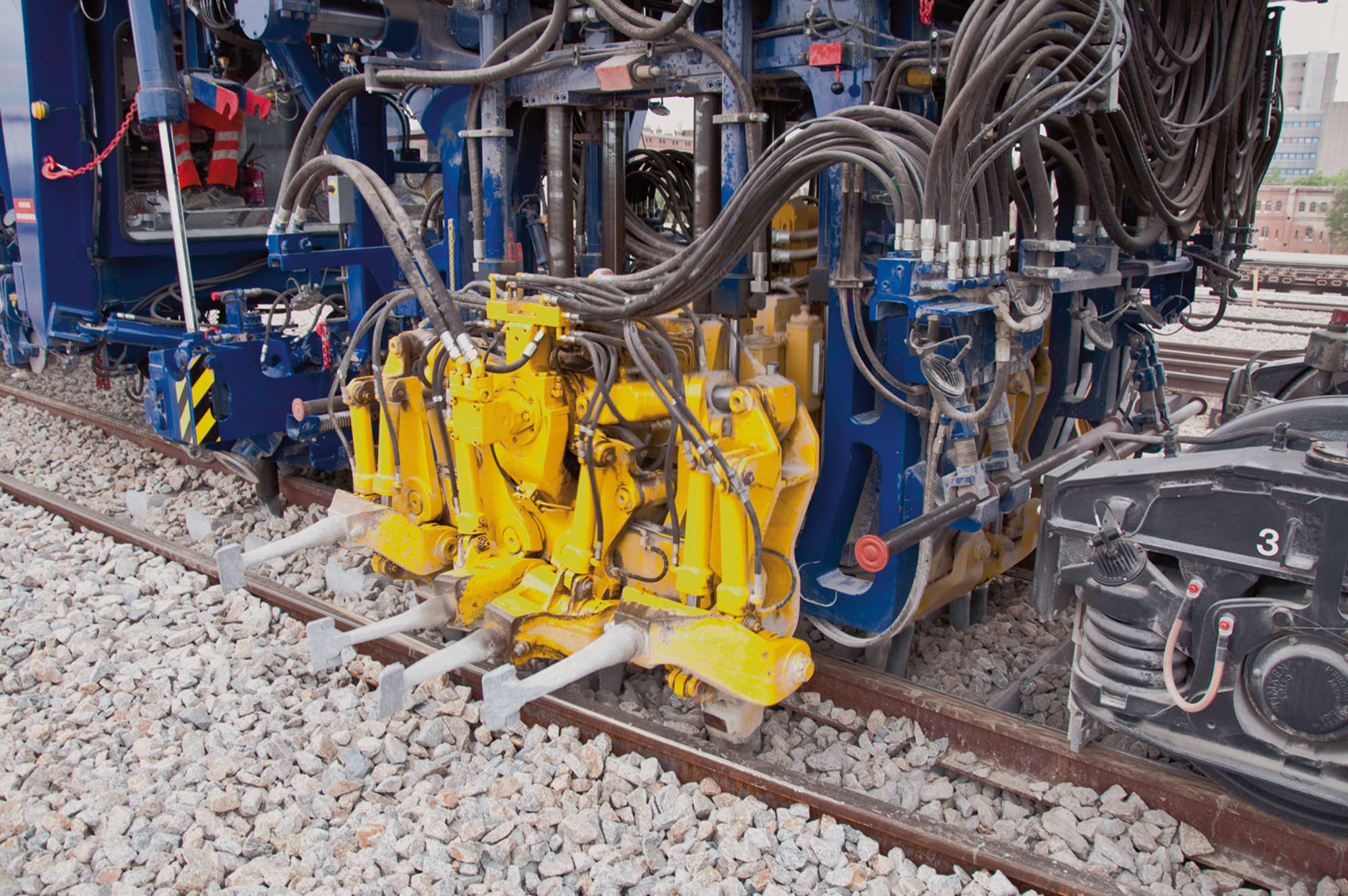
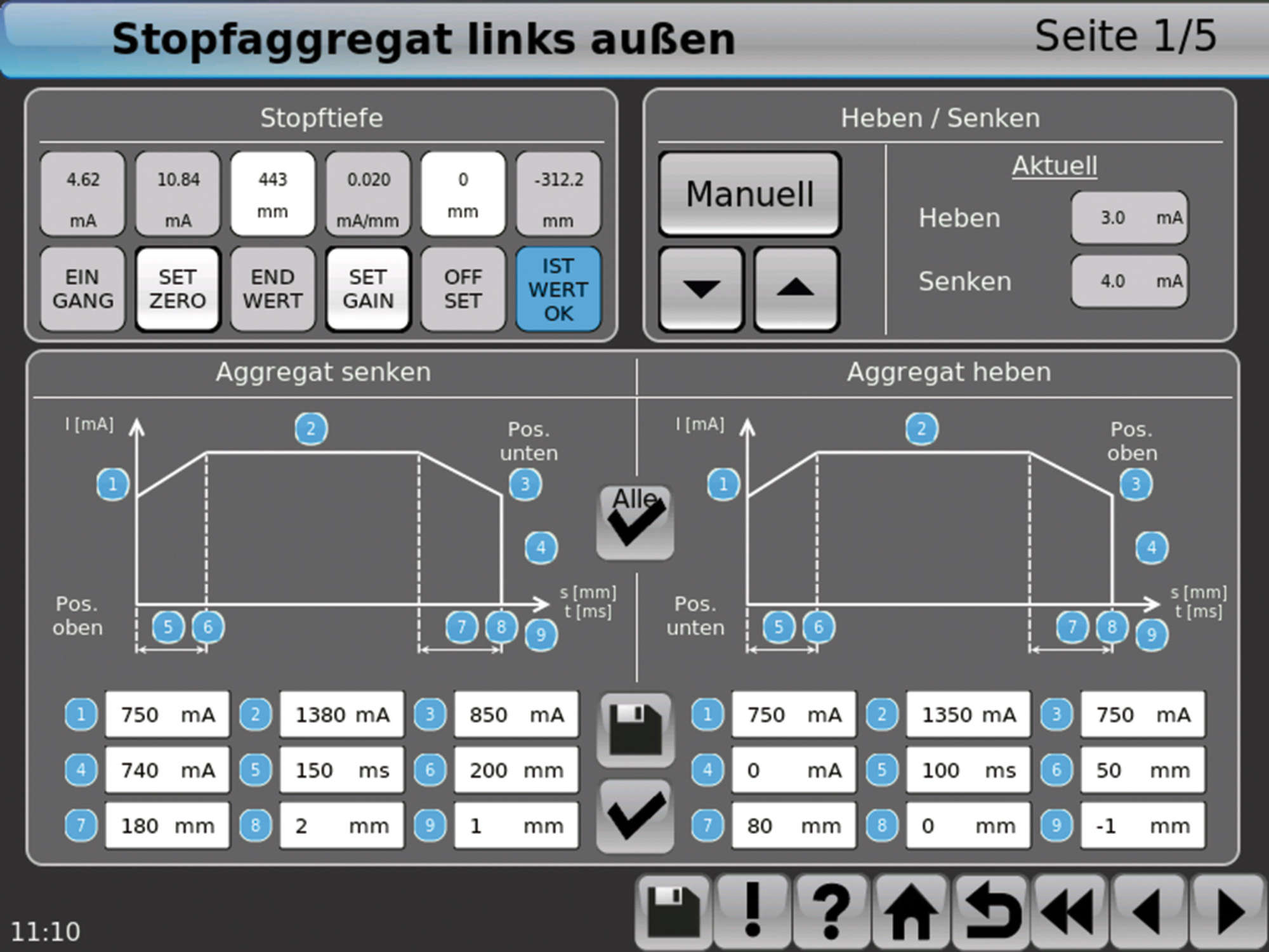
The right tamping depth is an important factor for the quality of tamping. This is why Plasser & Theurer developed an automatic device to guarantee exact observance of the tamping depth. The respective value is set from the operator’s seat and checked on the digital display.
When working on newly laid track, behind ballast cleaning machines or generally where large lifts have been performed, it is often necessary to repeat the squeeze movement of the tamping tines to produce a perfect sleeper bed. The automatic device performs this task: the units are raised briefly after the first tamping cycle and then lowered again immediately to squeeze a second time.
The tamping pressure is adapted to varying ballast conditions as tamping newly laid track requires a different tamping pressure than tamping an encrusted or solidly compacted ballast bed, for instance.
The operator can start off a complete tamping cycle by operating only a single pedal. When activating the pedal, the following actions are performed automatically:
A sleeper detection system (for track tamping) allows a fully automatic working cycle including forward motion control. If a certain spot cannot be tamped, a warning signal is given and the work cycle is stopped to make the adjustments that might be required. Optional equipment makes it possible to automatically detect double sleepers. In this case, the tamping units are adjusted fully automatically.
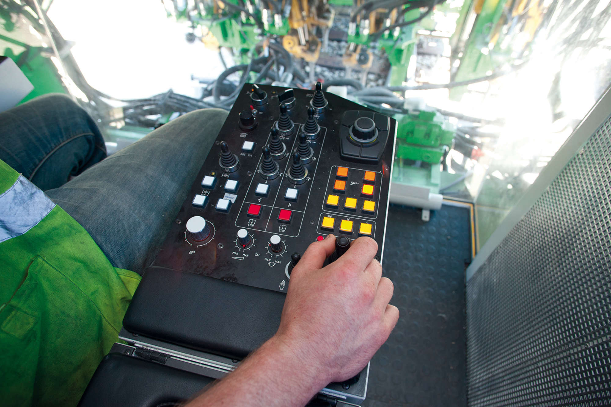
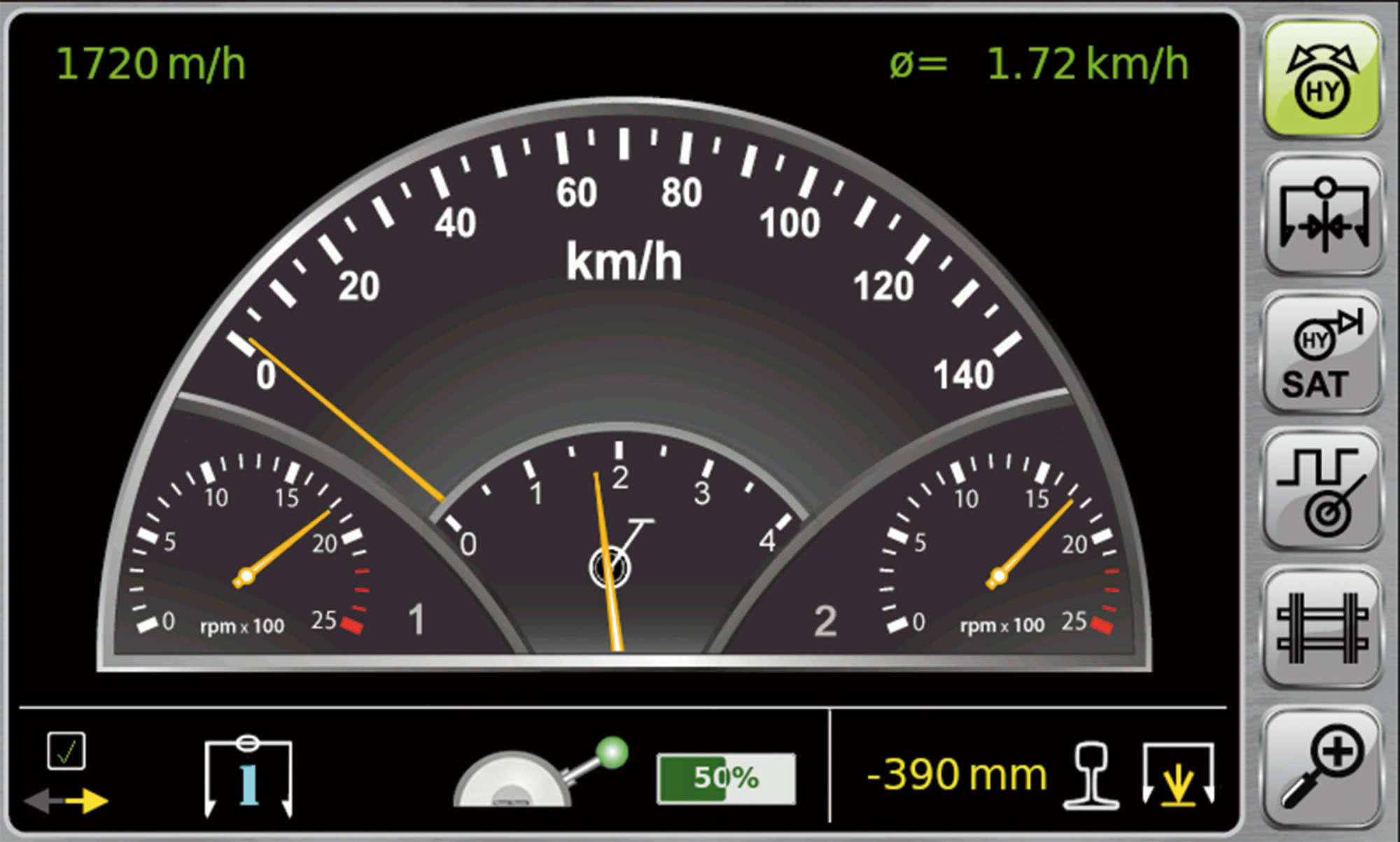
A digital display allows monitoring the tamping work optimally: using an additional pendulum the cross-level of the corrected track can be checked continuously (standard equipment for machines of the 09series). All switches relevant for the work process are positioned in the armrest of the seat. Alternatively, the touch panels can be operated via a display controller.
The integration of computer technology into track maintenance machines has automated and standardised many work sequences. Malfunctions can be detected and repaired more easily and quickly. The machines can be maintained more efficiently.
The machine control system consists of a digital control and the Plasser & Theurer microprocessor controller system for analogue control. Touch displays simplify adjustment and trouble-shooting.
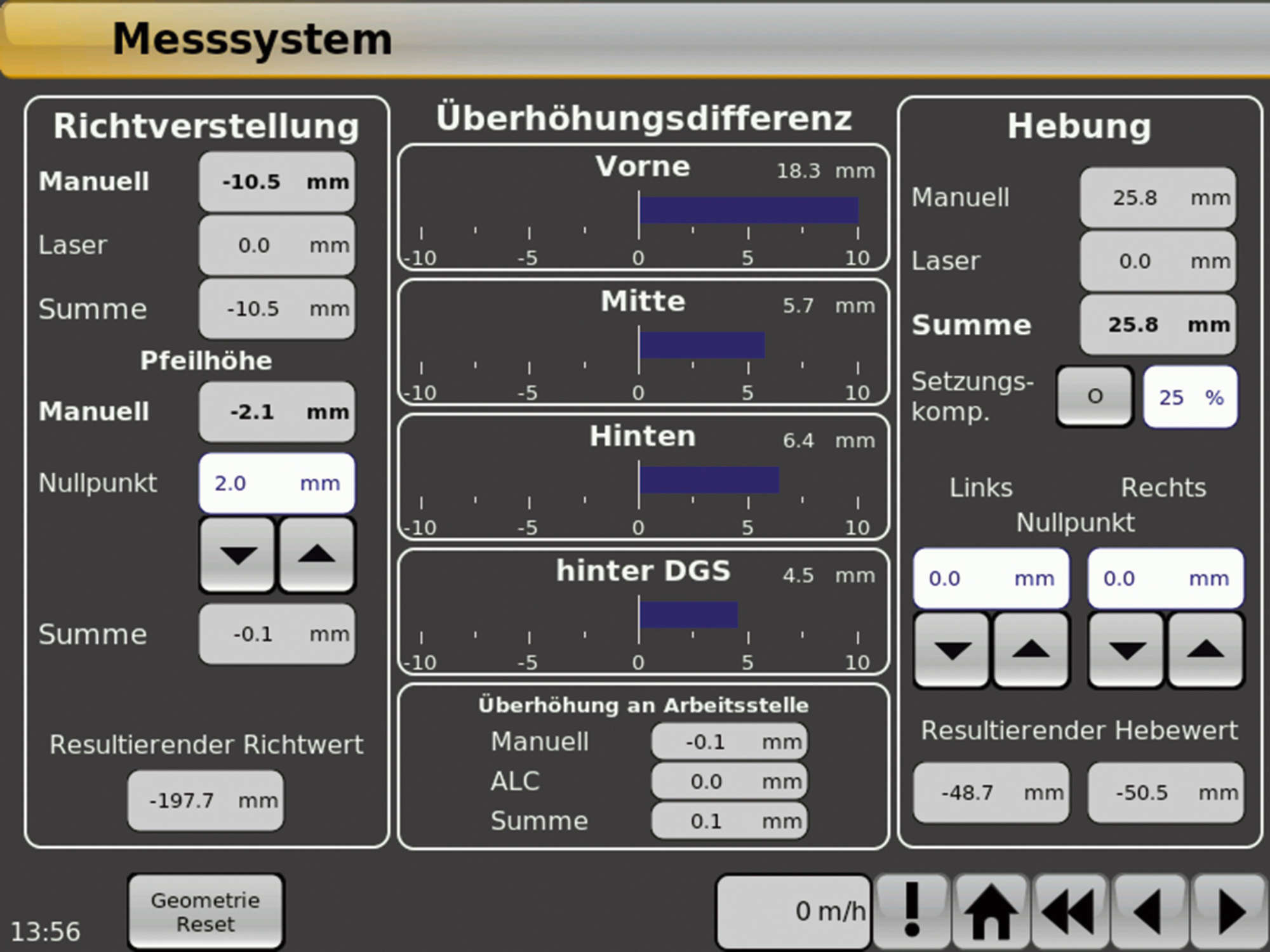
The CMS controller measuring system controls the levelling and lining unit. The CWS controller working system monitors and displays the drive control, the lifting/lowering of the tamping unit and the tamping pressure adjustment.
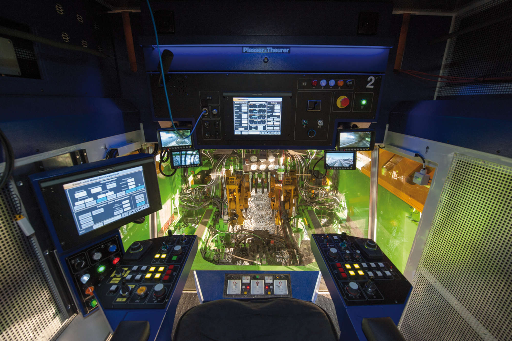
Plasser & Theurer’s intelligent control system is used for the control of subsystems and also for complete instrumentation and control solutions. The machine is operated either from touch screens offering a clearly arranged menu, or from the usual control desk.
This combination allows the operator central access to all machine functions. For the important main functions there are additional operating controls in the armrests which guarantee safe and faster operation. For better concentration on the task in hand, only the required functions are shown in the respective cabins.
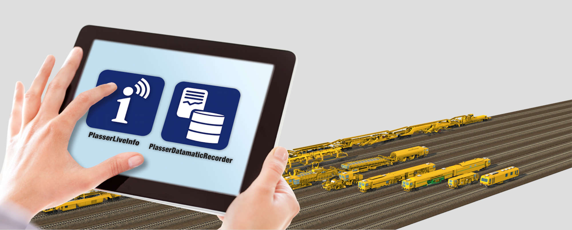
The innovative telematics system PlasserDatamatic opens new dimensions for the management of individual machines and entire fleets. It can be used to extend the P-IC 2.0 control system. Using a tablet or smart phone, the most important work parameters and status messages can be accessed at any time, no matter where you are.